Welcome to the Adosia knowledge base. Here you will find instructions to setup Adosia WiFi devices and answers to commonly asked questions
Introduction to the Adosia IoT Platform Where to watch Adosia DIY and How-To videos Where to get Adosia IoT WiFi hardware, sensors and accessories How to connect WiFi hardware to the Adosia IoT Platform Connecting components to the Adosia SPACE IO board Using relays with the Adosia SPACE IO board How to program Adosia hardware - IoT Device Profiles How to calibrate analog sensors Learn about Adosia (ADO) tokens How to support Adosia What's included in Adosia's FREE IoT account subscriptionAdosia lets you to create, manage, deploy and monitor customized WiFi control systems. Adosia pairs simple open IoT hardware building blocks with a freemium online platform - enabling a wide variety of personal, commercial, community and STEM education applications.
Get started with Adosia:
Adosia IoT Platform - Introduction Video:
You can view a number of DIY and How-To videos showing how to easily create all kinds of fun and useful IoT project on Adosia's Official YouTube Channel
Adosia WiFi hardware, compatible sensors and accessories can be purchased at the Adosia IoT Store (adosia.io)
If you are familiar with the Arduino IDE, you can use your own ESP8266 based WEMOS D1 R2 and WEMOS D1 Mini WiFi baseboard, but may benefit from purchasing a campanion Adosia SPACE IO board to enable more functionality
To use your own WEMOS D1 R2 or WEMOS D1 Mini WiFi board with the Adosia IoT platform you can download the latest Adosia binary by flashing the Adosia Phoenix Connect Script to your device using the popular Arduino IDE
Connecting new IoT WiFi hardware to the Adosia platform is easy:
Steps to connect IoT devices to Adosia:
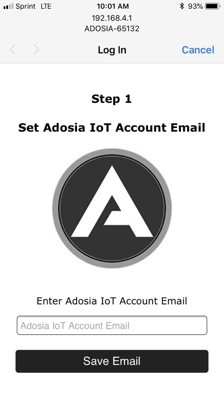
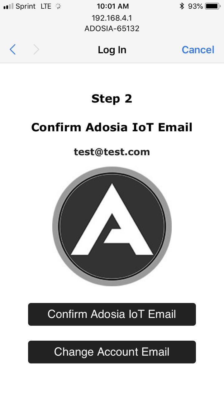
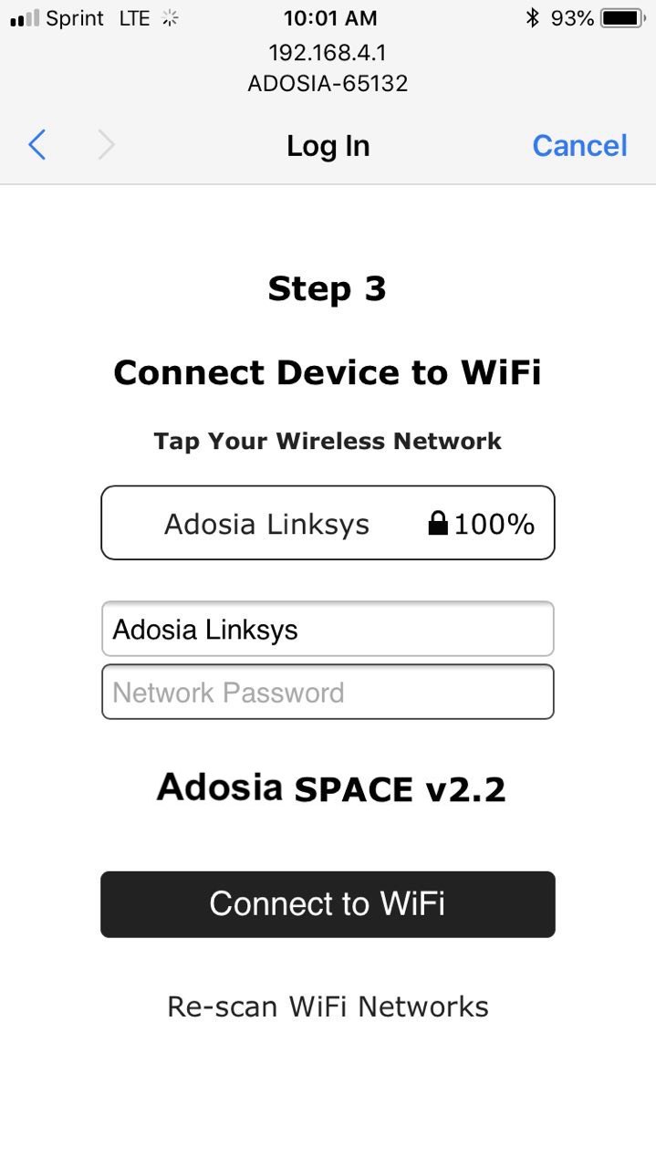
The device LED will blink green a few times when then device successfully connects to your WiFi network. If connection fails, exit your smart phone WiFi settings, restart your device, and try again
Adosia'a SPACE IO board is the first IO board released for Adosia's WiFi devices, and enables support for a wide variety of peripheral components and sensors
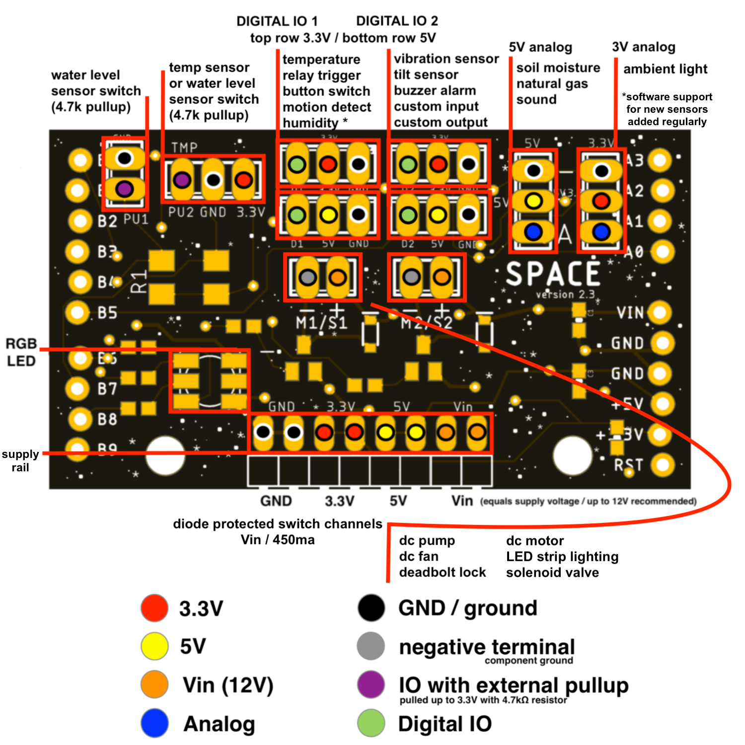
Motor / Switch Channel Locations:
The Adosia SPACE IO board has two (2) independent DC motor switch channels which can be used to drive a variety of motors, valves, switches and pumps. Each channel is diode-protected and can drive loads up to ~450mA at 12V (transistors rated ~600mA):
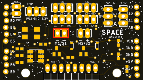
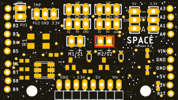
Motor / Switch Channel Component Options:
Digital IO Channel Locations:
The Adosia SPACE IO board has two (2) independent Digital IO channels to drive general digital input sensors / signals or output signals which can be used with a variety of components. For convenience, headers exist to use each of Digital IO channel with either a 3.3V supply (top channels) or 5V supply (bottom channels)
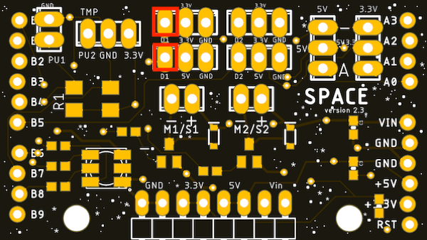
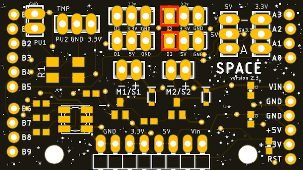
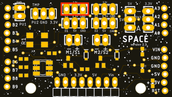
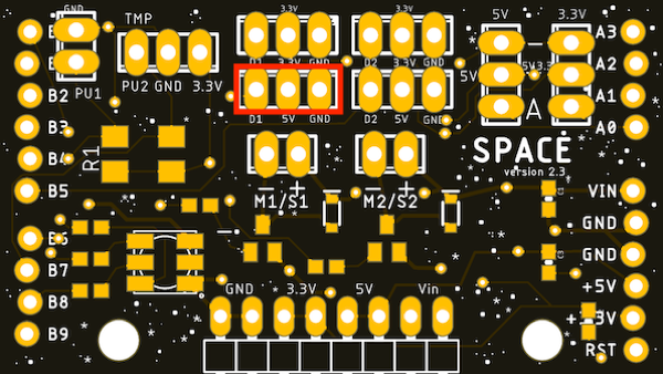
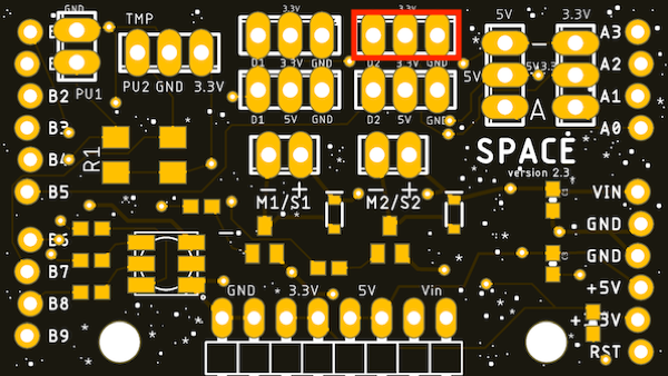
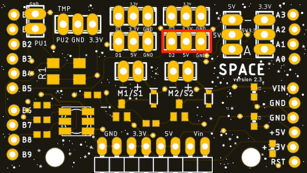
Digital IO Component Options:
Application-Specific Input Sensor Channel Locations:
The Adosia SPACE IO board has two (2) independent channels for application-specific input sensors requiring an external 4.7kΩ pullup resistor
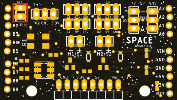
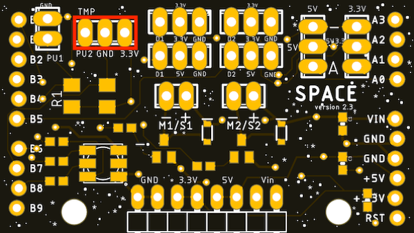
Application-Specific Input Sensor Component Options:
Water Level Sensor switches:
The SPACE IO board supports water level sensor switches on Pullup Channels 1 and 2.

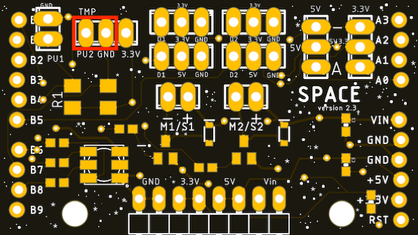
Temperature Sensors:
The SPACE IO board supports both submersible and ambient temperature sensors. Submersible temperature sensors are supported on Pullup Channels 1 and 2 (as they typically require a 4.7kΩ pullup resistor). Ambient temperature sensors are recommended to be used on Digital IO Channels 1 and 2 but can be used on Pullup Channels 1 and 2 with careful consideration for making proper GND and Vcc pin connections.
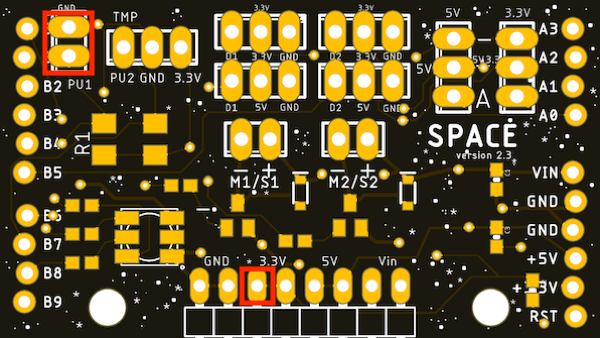


Analog Sensor Channel Location:
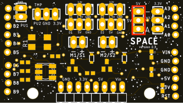
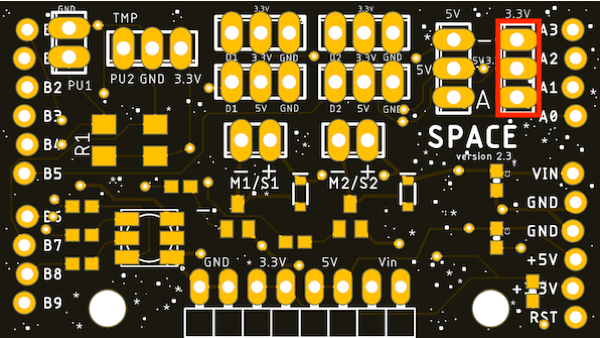
The Adosia SPACE IO board has one (1) channel to connect an analog sensor. The on-board connector supplies 5V to the sensor, and can support sensors requiring a 5V input supply voltage which outputs up to 3.3V.
connect 5V analog sensors directly to the analog connector with the black (ground) wire positioned towards the top edge of the board and the blue (analog) wire positioned towards the bottom of the board
Analog Sensor Component Options:
*some sensors such as the ambient light sensor must be connected using a 3.3V supply pin instead of 5V to ensure the sensor output does not exceed 3.3V
Relays components that can be tied to digital outputs and are used to switch higher power AC devices on and off. Relays greatly expand the capability of any system and can be activated using Digital IO #1 and/or Digital IO #2 set to General Digital Output when editing a device profile.
The relay module Adosia ships is activated using a LOW signal profile setting mode, and each relay can switch up to 15A at 120VAC or 10A at 220VAC. Supply 5V to the relay module allows the 3.3V output signals from the SPACE IO board to trigger the relay.
The relay module Adosia ships has 4 pins:
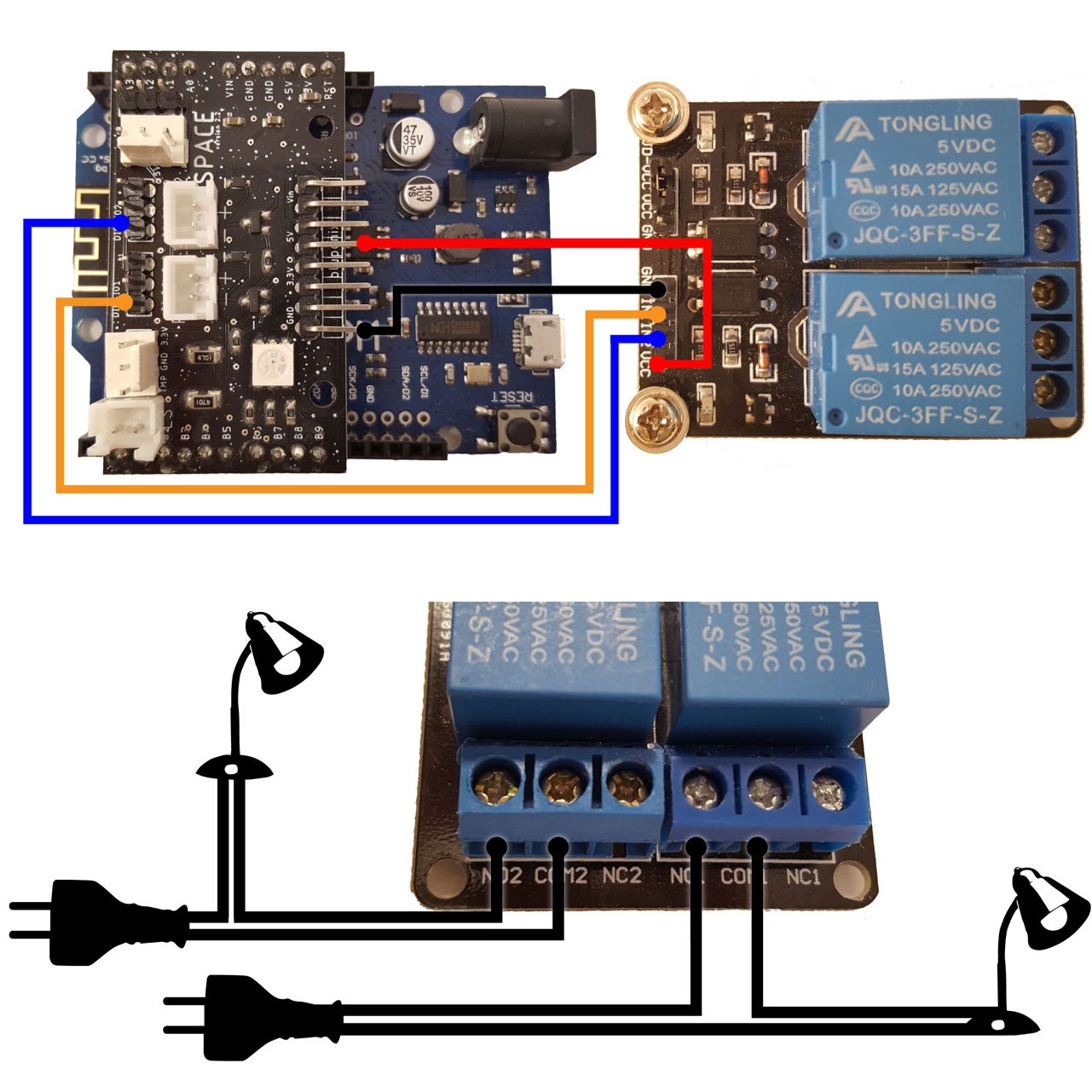
As an alternative to using the Adosia relay module, you could also use an IoT Relay adapter which accepts a digital IO input and makes it easy to plug in an AC power cord
Adosia IoT devices are programmed using device profiles that have been preconfigured for specific use cases by an Adosia platform user. You can create your own device operating profiles or purchase device profiles from other Adosia users. Device profiles enable multiple devices assigned the same profile to be easily managed. IoT device profiles can also be scheduled to dynamically activate at a specific desired time of day.
There are 3 main areas you can customize when programming the WiFi board:
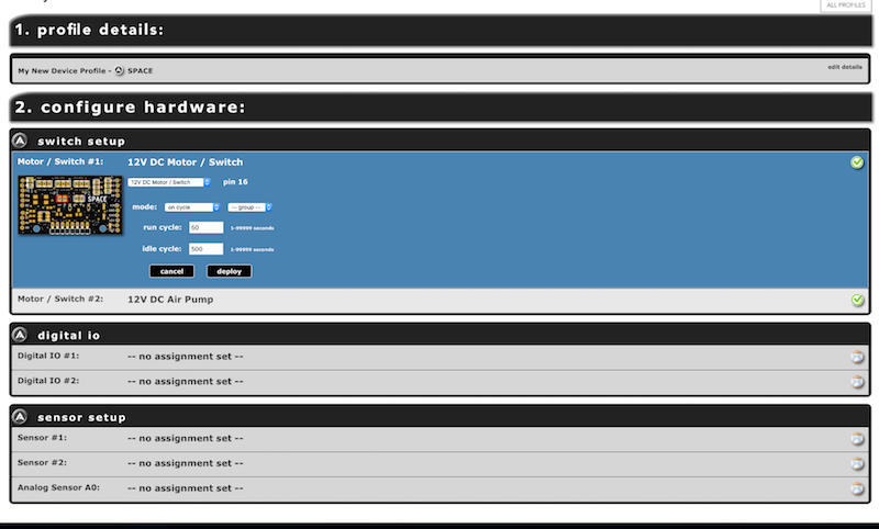
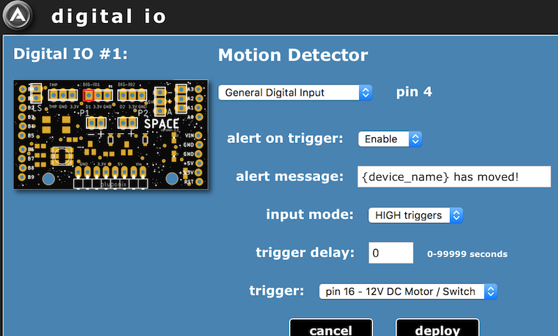
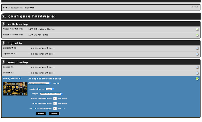
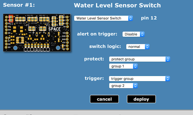
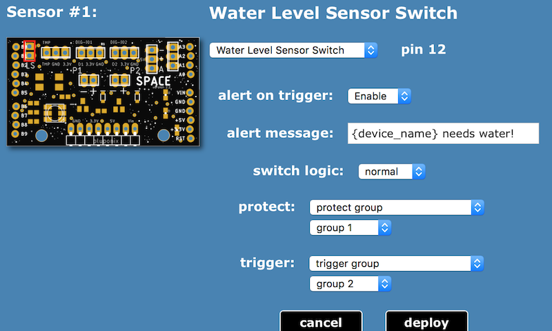
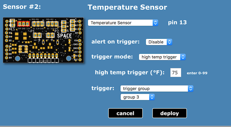
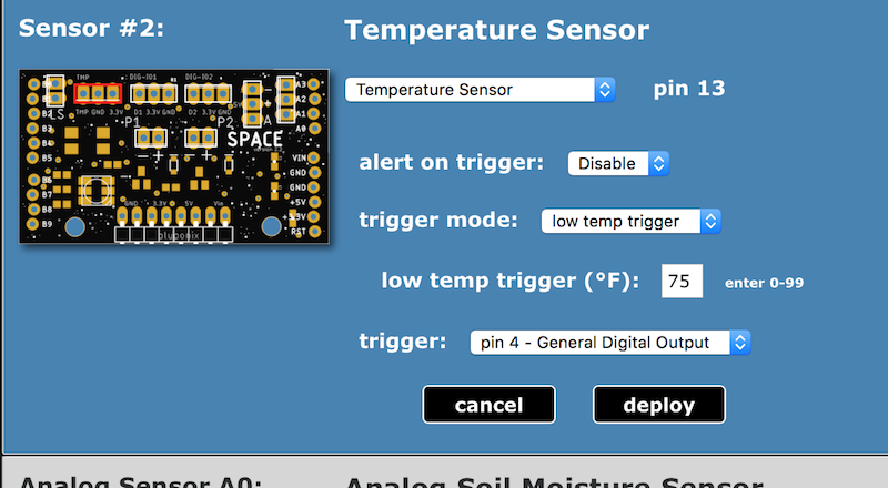
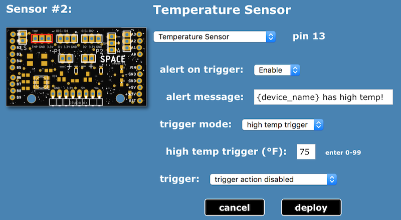
Each component plug-in or socket area of the board is highlighted by a red box on the board image displayed when specifying specific operating parameters for each area or pin of the board.
IMPORTANT - Once the deploy button has been clicked for each area, devices assigned to the newly configured profile will be set to update the next time each respective device checks in with Adosia's servers.
1. Motor / Switch Channels:
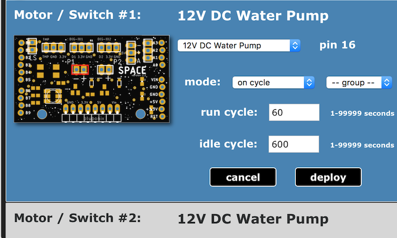
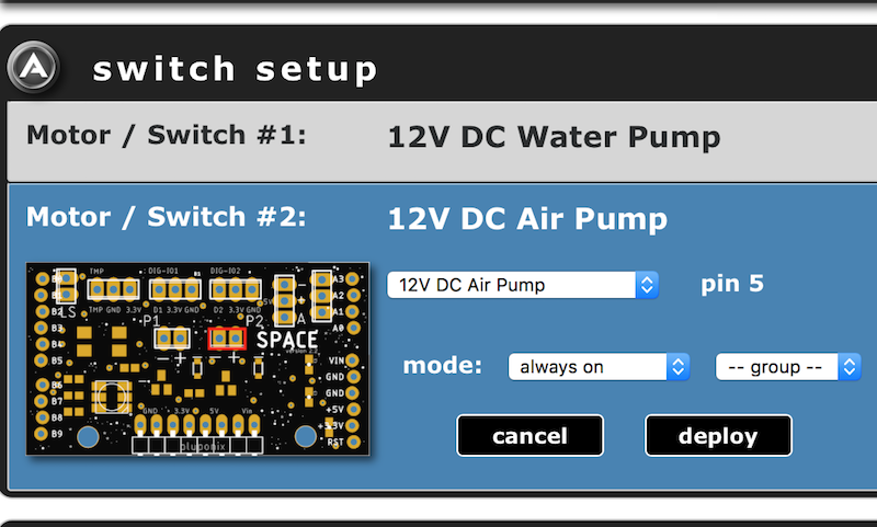
The Adosia SPACE IO board has two (2) diode-protected switch channels to safely drive components based on brushless DC motors and solenoids, such as pumps, motors, valves, locks. Each of these channels can each drive loads of up to ~450mA at 12V DC (transistors are rated ~600mA)
Motor / Switch Channel Operating Modes:
Motor / Switch Configuration Examples:
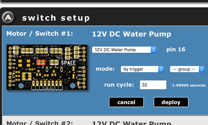
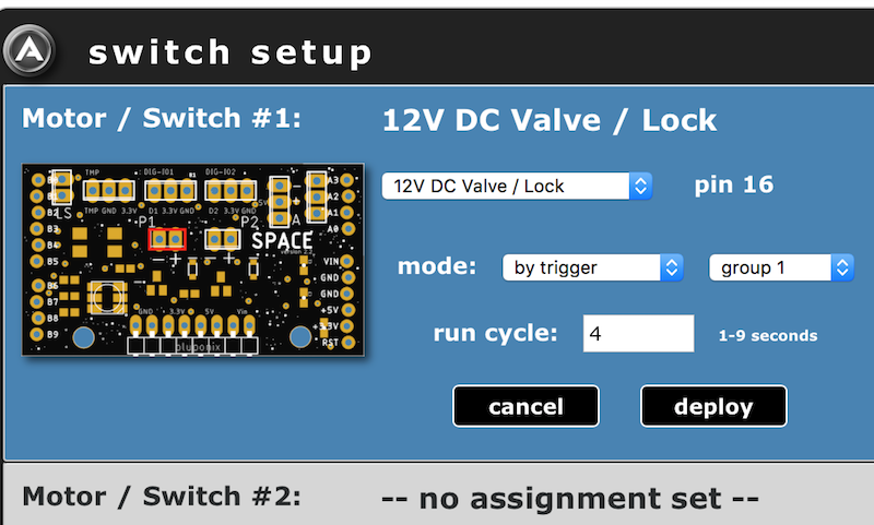
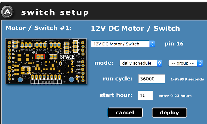
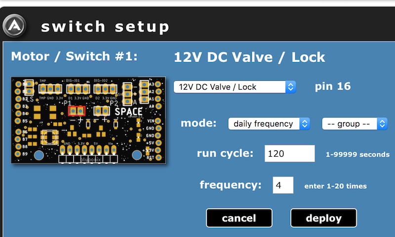
2. Digital IO Channels:
The Adosia SPACE IO board has two (2) channels dedicated to digital IO. These channels are rated at 3.3V can be configured to either digital input mode, digital output mode or motion detector. The maximum voltage on the pins is 3.3V (input or output).
Digital IO - Output Operating Modes:
Digital IO - Output Mode Examples:
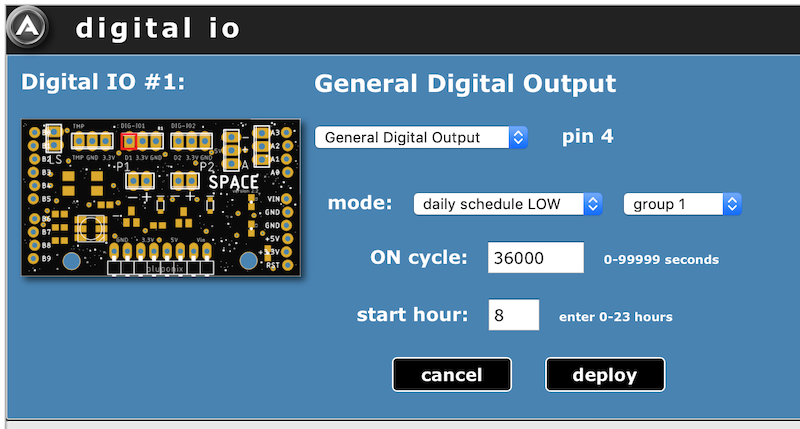
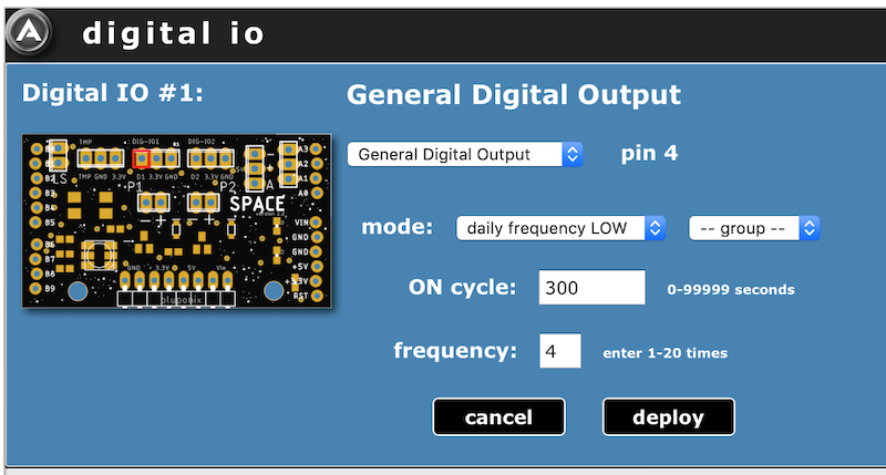
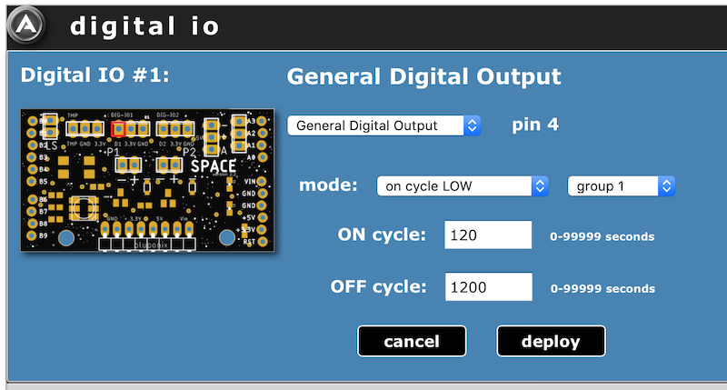
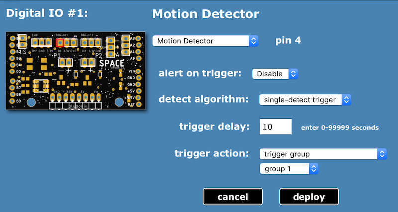
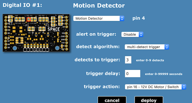
Digital IO - Motion Detector Modes:
Digital IO - Motion Detector Examples:
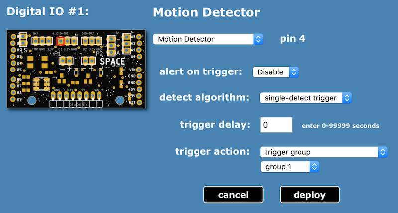
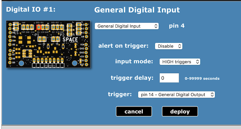
Digital IO - Input Operating Modes:
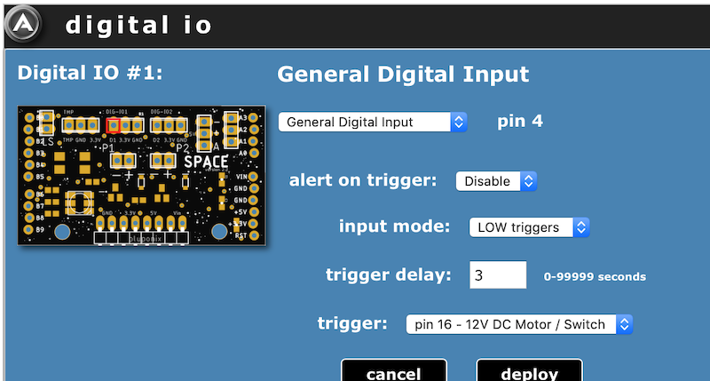
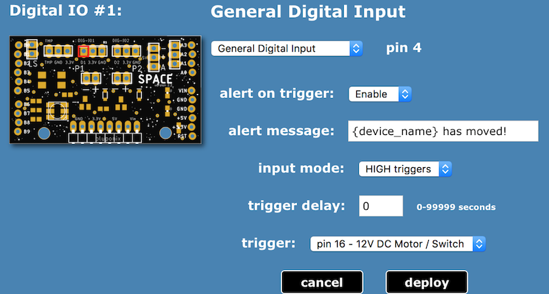
Digital IO channels utilize an internal pullup resistor when set to digital input mode, meaning the relevant pin will evaluate HIGH when no sensor is connected. To trigger an input on high, the attached input component (sensor or peripheral) should pull the signal low during non-triggering states.
Digital IO - Input Mode Examples:
3. Application-Specific & Analog Sensors:
The Adosia SPACE IO board has two (2) channels dedicated to application-specific sensors and supports one (1) analog sensor. Current application-specific sensors supported include water level sensor switches and temperature sensors. Current analog sensors supported include sensors to detect soil moisture level, natural gas levels, sound levels or ambient light levels.
Water Level Sensor Switch:


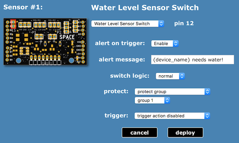
Water level sensor switches can be used to monitor state, to protect components (or component groups) from operating when triggered, and can trigger separate components (or component groups) into action whenever triggered.
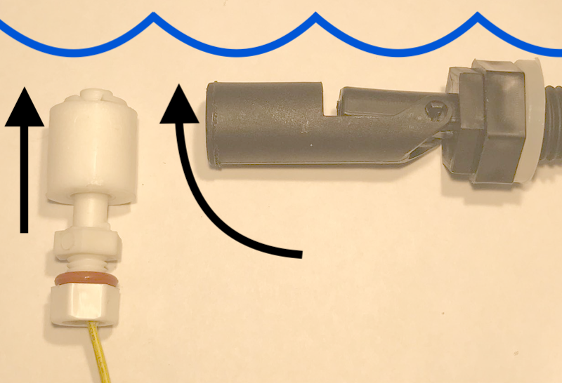
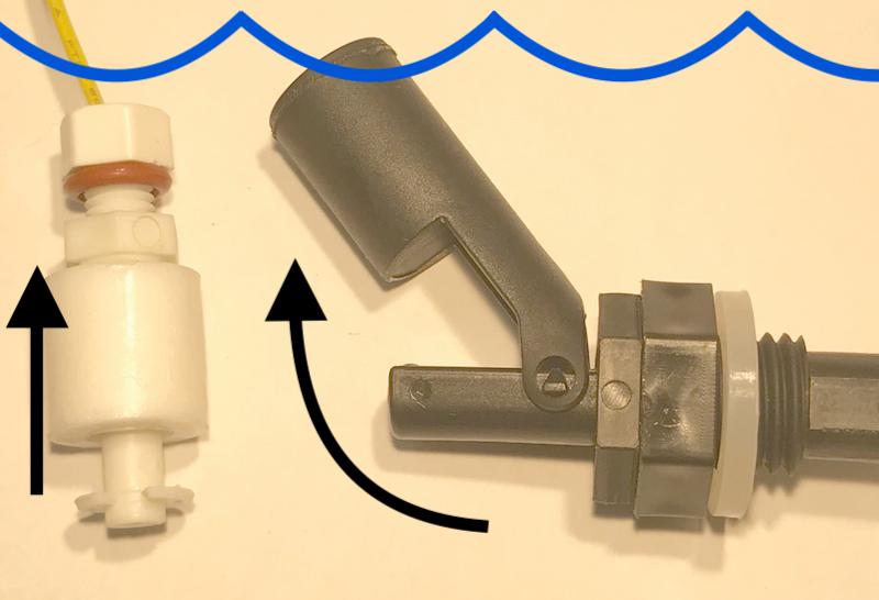
Water Level Sensor Switch Profile Examples:
Temperature Sensor:
Temperature sensors can be used to monitor temperature, and can trigger alarms and/or separate components (or component groups) into action at desired temperatures.
Temperature Sensor Profile Examples:
To calibrate an analog sensor you first must connect that sensor to measure the maximum and minimum readings that sensor could possibly measure when operating.
This will provide you the absolute maximum and minimum calibration values.
Narrowing the calibration range will increase the sensitivity between analog levels. This can be done by reducing the maximum analog calibration range value until the desired sensitivity is reached.
For example, when using a moisture sensor, you can adjust the moisture level sensitivity and increase watering frequency by reducing the analog sensor max calibration value.
Calibrating the analog Soil Moisture Sensor:
* a more accurate way to calibrate the moisture sensor would be to place the sensor in extremely wet soil (instead of submerged in water) and use that as a max wet reading and then in dry soil (instead of open air) for max the dry reading
Calibrating the analog Natural Gas Sensor:
Calibrating the analog Sound Sensor:
Calibrating the analog Ambient Light Sensor:
Adosia ADO tokens are a planned cryptocurrency feature to enable Adosia users to monetize their IoT creations. Currently ADO tokens may be used to purchase various account and device performance upgrades. Adosia users will soon be able sell or license their IoT profile creations to other Adosia users in exchange for ADO tokens. At that time ADO tokens could be converted into money to reward and incentive creative Adosia users.
Adosia has created an early-access incentive program to reward Adosia users with ADO token allocations whenever a new IoT device is connected to the Adosia platform or when new users are referred. Each time a user activates a new device, a "token lottery" will be conducted to reward that user's account with a random amount of ADO token allocations.
All free users receive the following:
upgrade for enhanced features and to increase device check-in frequency